Address
304 North Cardinal St.
Dorchester Center, MA 02124
Work Hours
Monday to Friday: 7AM - 7PM
Weekend: 10AM - 5PM
Address
304 North Cardinal St.
Dorchester Center, MA 02124
Work Hours
Monday to Friday: 7AM - 7PM
Weekend: 10AM - 5PM
Analytical relationships for flow rates versus pressure, which apply to the flow of plastics materials, are shown in Table 10.1. However, this table is a strict application to Newtonian fluids, where the resistance to flow is independent of the shear rate, and the viscosity is a constant—a condition that does not prevail for polymers. At higher shear rates, the polymer molecules (and short fibers in filled plastics) become aligned, and the resistance to flow is reduced. Aligned molecules and/or fibers, coupled with reduced resistance to flow, translates to a lower viscosity. In order to use the mathematical approach, it becomes necessary to adjust for this reduction in viscosity as the shear rate increases. The viscosity of the plastics material is 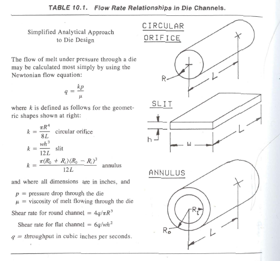 s0 temperature-dependent. The flow through the die causes shear in the material and generates frictional heat. The amount of heat generated must be considered in the design of the die. High shear regions in the die will result in lower viscosity, which in turn will result in higher relative flow rates of the plastics material.
Data on the previously mentioned criteria is reported in the literature on curves .If sufficient data are available on a specific material, it is possible to use the equations in Table 10.1 to accurately define the shape of the flow channel required to produce the desired extrudate. Computer Aided Design (CAD) programs are becoming increasingly available to perform analysis for die design. Most of the CAD programs currently listed in trade literature are for sheet and tubing products. Even computer analysis needs evaluation and modification based on prior experience. Analytical judgment is also required in using the simplified relationships between channel depth, channel length, and flow rate as a guide to the “correct” design. Practical experience is most needed when designing a die for profile shapes where the flow can be quite complex.

Another complicating factor in die design is die-swell. When a plastic material emerges from the die lips (orifice), the material swells to a dimension larger than the die opening. The swell occurs as a result of energy stored in the plastic material, i.e., elastic energy. The amount of die-swell will vary from one material to another, and will also vary with changes in the operating conditions for the extruder (the speed of screw rotation, temperature of the barrel or screw, backpressure, etc.). Depending on the material and the melt conditions, die-swell will range from less than 5% to over 100% of the orifice dimension. Once again, we repeat that there is no Substitute for practical experience. Estimating of die-swell resolves itself to an ‘educated guess.”
The design procedures use these relationships: flow will vary as the cube and inversely as the channel length (L) with any given upstream pressure. These relationships are used in many ways, ranging from the “rule-of-thumb,,calculations of the flow character of a particular die channel to the exacting computer-generated design analysis that defines the shape of the die opening, the orifice dimensions, and the precise shape of the interior flow channels in the die.