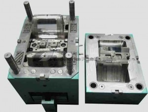
 Manufacturing an injection mould tool requires a high level of skill, and the success of an injection moulding tool depends jointly on the design of the tool,the skill of the toolmaker and the moulding technician. It is desirable, although not essential, for a tool designer to have had some experience of toolmaking. If the designer does not have direct experience, then at least an appreciation of toolmaking techniques and problems is necessary.
The same observation applies to toolmakers. Ideally, they should spend some time in an injection moulding production environment, to observe at first hand how tools perform and to observe the problems encountered. It is essential, however, for the mould designer to have both experience and knowledge of materials and injection moulding techniques.
All production tools should be made from high-quality steels manufactured to suitable BS, ASTM or DIN standards.
Several different metals are sometimes used, but the majority of mould tool metals used fall into three groups:
- Nickel—chromium alloy steels (H13 ASTM or BS EN30B)
- Mild steels or low-carbon steels (BS EN8) or those of higher carbon con tent
- Beryllium-copper
The following guidelines apply to all mould tools:
- All tool plates should be ground flat and parallel, and preferably the grade of steel and an identification number should be marked on them for future reference.
- Provision should be made for aligning the tool by means of extended guide bush systems or by separate alignment dowels. This enables the tool to be taken to pieces and then reassembled correctly.
- All sliding mating sliding surfaces should be fully hardened and should be of different degrees of hardness from each other
- All ejector pins should be hardened. Nitrided pins are used for most situations, but where any flexure is likely to occur Tuftrided pins are preferred.
- Tools should have a relief area ground around the cavity positions to concentrate the locking Force on a smaller area. See Chapter 20 for a full discussion of this topic.
- Retaining catches must be used to hold side cores or splits in position after they have opened.
- Adequate provision must be made for water cooling (or oil heating).
- Lifting holes or bars should be provided.
- All surfaces with which the moulding material makes contact should be highly polished in the direction of flow. Cavities should be polished in the direction of draw unless a textured finish is required on the mouldings.
 Manufacturing an injection mould tool requires a high level of skill, and the success of an injection moulding tool depends jointly on the design of the tool,the skill of the toolmaker and the moulding technician. It is desirable, although not essential, for a tool designer to have had some experience of toolmaking. If the designer does not have direct experience, then at least an appreciation of toolmaking techniques and problems is necessary.