Address
304 North Cardinal St.
Dorchester Center, MA 02124
Work Hours
Monday to Friday: 7AM - 7PM
Weekend: 10AM - 5PM
Address
304 North Cardinal St.
Dorchester Center, MA 02124
Work Hours
Monday to Friday: 7AM - 7PM
Weekend: 10AM - 5PM
Sheet plastics are made in thicknesses ranging from 0.010 in. to 1.0 in. or more, and in widths of 120 in. or more. The die orifice is a slit of the appropriate height and width (plastic sheet is nearly always extruded in a horizontal position—thus height refers to the thickness of the sheet). The design effort is directed toward producing a suitable internal channel inside the die to achieve “proper” distribution of the melt, entering from the screw-tip, to the die-lips in order to produce a uniform thickness of material exiting from the die-lips and along the full width of the die. (Note: We use the term “die-lips” when discussing “sheet” whereas we use “orifice” when referring to “shaped” output.) To assist with the regulation of material flow, the die is equipped with adjustable restrictions along its width. These restrictors permit adjusting for spot changes in sheet thickness by changing the flow pattern in the die. In most sheet operations, the output of the die is fed to a three-roll calender stack where the entering nip-roll spacing controls the final thickness of the sheet. Without the restrictors, as mentioned above, the excessive variations along the width results in the nip-roll forcing the plastics material sidewise instead of stretching it. The side movement of the plastic produces an unacceptable “smearing” of the sheet and could result in reduced physical properties.
The simplest manifold in use with sheet dies is the T Shape shown in Fig. 1. The melt enters from the extruder screw and on the leg of the “T” The melt is then distributed to both sides on the cap of the “T” The downstream side of the main channel in the manifold is open, but with a restriction, to feed the melt to the die-lips.
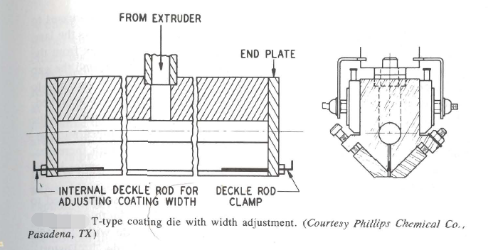
Fig. 1.
The T-shape manifold may be an erratic performer in sheet extrusion because of the variable pressure drop along the main manifold. The rate at which the material flows is a function of the pressure drops along the flow path. Thus the longer flow path to the end of the T manifold results in a lesser flow of material as it approaches the ends of the manifold. Correction of this unequal flow is usually achieved by a narrow opening at the center of the die and a gradual increase to the wider opening at each end of the die.
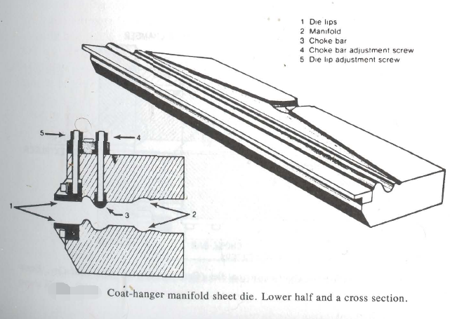
The coathanger is the most frequently used design for the extrusion of sheet products. In this design, a triangular preland restriction is introduced into the flow path. The distributor manifold is shaped like a ‘‘coathanger,,’ thus the descriptive name. The plastic material first flows into the manifold behind the pre-land section. Then the plastic melt moves across the pre-land in the direction of the die-lips. The pre-land distance to the die-lips is longest near the center of the die. It decreases to its shortest distance at each end of the die. The pressure drop across the land is equalized to a nearly constant pressure as the material emerges from the die-lips. By appropriate selection of the angles of the pre-land, and the gap in the pre-land area—usually about two to three times the die opening—to match the polymer rheology, a balanced flow to the die-lips is achieved. The “coathanger” will give better results than the T-shape described in the previous paragraph. The selection of the “coathanger” becomes more attractive as the sheet thickness increases and as the sheet width increases. One of the references details methods for calculating the channel in the “coathanger” manifold.