Address
304 North Cardinal St.
Dorchester Center, MA 02124
Work Hours
Monday to Friday: 7AM - 7PM
Weekend: 10AM - 5PM
Address
304 North Cardinal St.
Dorchester Center, MA 02124
Work Hours
Monday to Friday: 7AM - 7PM
Weekend: 10AM - 5PM
Fig. 1 illustrates a die equipped with a choke bar assembly used to compensate for flow variations that may exist across the width of the die. The final adjustment for extruded sheet thickness is made with the “die blade adjustment screws,’ to distort the ‘‘adjustable die blade.” “Distort” means the adjustable die blade may not be straight, and it may not be parallel to the fixed die blade.
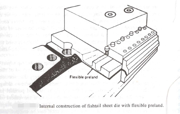
Fig. 1
Two additional refinements in the design of dies for sheet extrusion are used when a material has a complicated melt rheology, and when the material is highly sensitive to shear. One of these modifications is the tapering of the manifold diameter to a smaller diameter as the distance from the melt entry point increases. Tapering provides a variable pressure drop condition that improves the distribution of the melt along the die width. The second modification is to create the manifold as a curve rather than a straight line.
A curved manifold will result in a curved pre-land barrier. Choosing the proper curve, and perhaps including taper at the same time, can enable a closer match between the pressure drop and the melt rheology. Sheet dies with curved and tapered manifolds are called “fishtail” dies because of the resemblance of the manifold to a fishtail shape. Another of the references at the end of this chapter describes the finite element flow analysis used to determine the shape of the manifold, and the size and shape of the pre-land area as applied to a specific extrusion material.

Fig. 2
An improved, but more expensive, method for making the die-lip adjustment is illustrated by Fig. 2. A flexible upper lip is used instead of the adjustable die blade, or Fig. 1. The upper die-lip has a very thin section capable of being deflected by the downward adjustment of the screws along the top side. The (“normal” condition of the top lip is flat and parallel to the bottom lip, and the adjusting screws prevent the upward movement of the lip when it is under pressure from the extrudate. The major advantage of this design is the lack of a joint where the hot melt can be trapped and decomposes. A secondary advantage is the ease of adjusting the die opening to control the extrudate thickness along the width of the sheet.

Figure 3
Figure 3 illustrates how the choke bar can be eliminated and replaced by a flexible pre-land section of the die. A flexible pre-land section is particularly useful when materials highly sensitive to variations in heat, such as rigid PVC, are being extruded. The pre-land space is adjusted by increasing or decreasing the pressure of the individual screws along the width of the die.
A clear line of demarcation between the tooling and its operation is lacking, as we consider the many innovative ways in which adjustment can be made by increasing the sophistication of the individual elements of the die or its controls. For example, Fig. 2 illustrates the AutoFlex® die design. The die bolts, which press on the flexible lip of the die, are fixed at the head-end. Electrically heated “bolt-heater blocks,,are applied to the individual bolts. Each of the electric heaters is controlled by a closed-loop console activated by the sheet thickness emerging from the die. Such controls allow the expansion or contraction of the pressure bolt to continuously and automatically adjust the die opening to compensate for a variation in sheet thickness at any given point along the entire die width. Close control of the thickness of any sheet coming from the die results in close control of the product dimensions.
The sheet dies are equipped with heaters to heat the entire die to operating temperatures, and to maintain the dies at a given temperature. Figure 10.8 illustrates the application of cartridge heaters usually employed for this purpose. Most catalogs of suppliers of electric heater elements also contain the formula for calculating heat losses, watts per sq. in., and other information needed to determine the “correct” size, placement, and wattage needed to raise the die to operating temperature in some “reasonable” time and to maintain a given temperature without either the die overheating or the electric heaters excessively on-off cycling. The authors recommend that each designer study the catalog formula and follow the suppliers’ recommendations.
An extruder for thick or wide sheets is quite large equipment. Obviously a die made of steel and 10 ft. wide (long) is a heavy piece of equipment. Dies are bolted or taper locked to the end of the barrel. Most dies are also equipped with a support structure to carry some of the die weight and relieve the stress on the main extruder. The die designer will probably be called upon to design some of this auxiliary structure.
We have previously mentioned the ‘‘three-roll stack,,as part of the takeoff mechanism for extruding sheet stock. The three-roll stack performs at least three functions in producing the final sheet. First of all, the top rolls act as a calender to reduce the extrudate to the “correct” thickness. A portion of the thickness reduction is also enabled by control of the rotational speed of the rolls. At the same time, reduction is taking place, the sheet is being cooled. Roll temperature is controlled by the circulation of a controlled temperature fluid through the rolls. The functions of a three-roll stack are calendering, pulling (or stretching), and cooling. Designing and Building three roll stacks is an art all its own. The die designer should have a good working knowledge of the limitations (or capabilities) of the three-roll stack. Most of the newer lines will be equipped with computerized control of roll speed, temperature, and spacing adjustment; and include computerized control of the extruder processing conditions of temperature, screw speeds, die adjustment, and so forth.