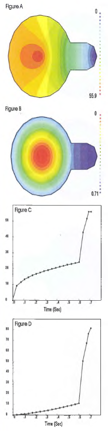
In many injection molded parts it is not feasible to avoid filling imbalances; however, the imbalances can often be minimized. The part presented in Fig.1 left develops many of the conditions discussed earlier. The injection molds gate in this part is positioned in the center of the main cylindrical body. This would be ideal if it were not for the appendage on the right side of the part. The appendage creates a situation where the melt reaching the perimeter of the main cylindrical body approaches a hydrostatic condition, redirecting the melt to the continuing flow front in the appendage. Following clockwise from the top left:
- a) At the instant the main body is filled, the early filling regions approach a hydrostatic condition (note the wide spacing in the isobars in this region indicating a more constant pressure with a minimum pressure gradient)
- b) The flow front accelerates into the appendage (notice the dramatic increase in the flow front indicated by the wide spacing in lines)
- c) The acceleration into the handle causes a pressure spike (plot of Pressure vs. % Fill). This pressure spike increases fill pressure from 23 MPa to 57 MPa (2 Vi times increase) during the last 12% of fill.
- d) The pressure spike compounds the high pressure condition in the hydrostatic regions causing the force within the cavity to increase dramatically – which in turn will increase tonnage requirements (plot of Clamp Tonnage vs. % Fill). Clamp tonnage increases by over 600% during the last 12% of fill.
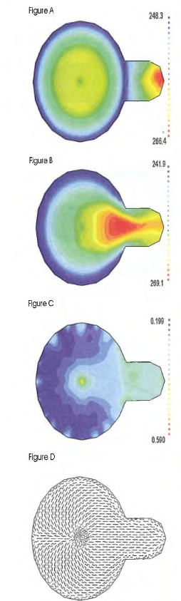 Further evaluation of the effect can be seen in Fig. left Again, clockwise from the top left:
- a) The increased velocity and shear causes the flow front temperature to spike as the melt enters the appendage: A sudden increase of over 18 °C can be observed. This is in contrast to the reduction in temperature occurring just prior to entering the appendage.
- b) The effect on the melt temperature distribution is even more
dramatic at the instant the plastic mou ld fills. The material in the early fill
regions has had a chance to cool a bit more, while the entire path
between the gate and end of fill can be seen to spike in temperature, reheating some of the material that had previously been losing heat. Temperature variations within this part reach almost 30 °C.
- c) The increase in velocity in the handle causes a high shear stress to
develop between the gate and the appendage. Note that the shear
stress spikes to about 0.400 MPa as the material first enters the
appendage and then drops to about 0.300 MPa as the melt
temperature spikes.
- d) Significant transient flow, or changes in flow direction, is developed
in the early-filled regions. This can be seen by contrasting the filling
pattern indicated by the flow angle lines in this figure to the original
fill pattern shown in Fig. above. Also note the changes occurring in
the early fill regions as opposed to the direct line of flow between the
gate and the later-filling appendage.
Reflecting on the factors affecting the development of residual strains
and shrinkage of a plastic part, it is apparent that the imbalanced filling
will create extremely complex strain patterns through the cross section
of this molded part, as well as between different regions of the part. This
part would be very sensitive to warping. When considering alternate
gating, one would realize that there is no ideal position in a part with
this non-symmetrical geometry. However, there maybe better positions.
An edge gate on the right side would provide a more uniform flow path
across the part and hydrostatic regions would be virtually eliminated
. More appropriate fill rates would provide more uniform
melt temperature and shear stress conditions throughout the part.
Another alternate gating location would be in a balanced position
between the left and right extremities of the part. This would reduce
some of the imbalances, though they could not eliminate the remaining
imbalance between the vertical and horizontal directions in the part.